Showing posts with label RC Car. Show all posts

Keep Track of your Shock Pistons

Keep Track of your Shock Pistons
The major manufacturers have done us a great service by molding the shock piston hole size on the pistons to help identify them when building (or tuning) our shocks. The problem is, especially for us old guys, that it’s really hard to read them sometimes. Worse yet, if they’re already IN your shocks, the oil (whether it’s clean or dirty) makes reading them even more difficult.
I’ve been using this simple procedure for years now and it works great. Simply take a Sharpie (preferably black, but any color will do) and color over the face of the piston where the number is. The number will stay white and be extremely easy to see, even after the shock has been built.
Oh, and don’t forget to do this PRIOR to building the shocks. Sharpies don’t like oily surfaces!

Nitro Engine Storage

Engine Storage Materials
While many engines always have a home in the vehicles that they are used in, there are a lot of drivers that may have a spare engine waiting to go, either for racing or as a back-up for a basher vehicle. For those that do, we hope you are properly storing that expensive mill so nothing happens to it while it’s waiting for its turn in the engine mounts. Here, we’re going to give you some simple tips to properly store your nitro powerplant.
WHY PREP YOUR ENGINE FOR STORAGE?What could go wrong while an engine is in storage you ask? Plenty! If an engine is stored too long, there is a chance that unburnt fuel sitting in the engine or bearings can evaporate over time and, along with temperature changes, can start to turn the oils into gunk that can clog up and cause friction in the engine. Moisture is also a threat to any steel parts within the engine and finally, there is debris. You know, dust and dirt, which can make their way into any part of your vehicle, such as the engine’s carb or exhaust, and once in there can damage the engine when you fire it up. So lets talk steps to keep your engine protected.
After Run Oil
OIL IT- The first step for engine storage is adding a number of drops of a good after-run oil. An after-run oil is much less likely to turn into that nasty gunk over time and it coats your engine internals to protect them. Add a few drops down the carb venturi as well and then add a few more into the exhaust port if it’s exposed. Or you can take out the plug, drop oil in the top of the chamber and replace the plug.
Engine Caps
CAP IT- When you’re done adding after-run oil to the inside of the engine and you’ve rocked the crank back and forth a few times to coat the internals, it’s a good idea to ensure the oil stays in. Use caps, such as these shown here from TrakPower, to keep the oils in. Capping will also keep the debris out of your mill while it sits in your pit bag or on your bench. Cap the carb venturi, fuel nipple and exhuast port. If your exhaust is still fitted to your engine, add caps to the exhaust stinger and pressure nipple.
Seal Engine In A Bag
BAG IT- Now that your engine has been oiled and capped, its a good idea to place it in a plastic bag along with a silica gel packet and zip it closed to keep moisture and debris away from the engine.
Outerwears Engine Bag
GOING OVERBOARD- Looking for that extra bit of protection during storage? Consider an engine bag from Outerwears. This fabric bag with an inner liner keeps your engine neatly stowed and secured inside with its Velcro closure.
WRAP UP
A few simple steps and a few neat products are all you need to keep your engine stored and safe. Take the time to care for your engine and it will be there, ready to go, when you need it!

How To: Spend Wisely! Eleven Tools Totally Worth the Money

by 
The RC car industry is full of innovative products—many of which are geared toward wrenching-oriented tasks. Over the years, many tools and accessories have been developed with RC use in mind, and others although non-RC specific, lend themselves extremely well to RC use. Some RC tools are a bit expensive. While some may scoff at spending $20 on a single hex wrench, or $150 on a soldering iron, many of these products are actually worth the money in the long run. The following is a list of some of the best tools and wrenching accessories that are worth the splurge.
High-quality wrenches and drivers
wrenches and drivers
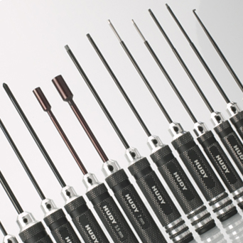
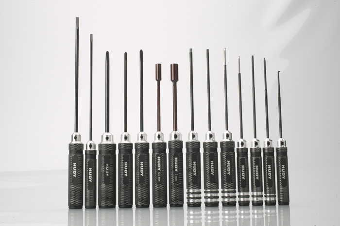
A great place to splurge is on high-quality aluminum wrenches. Ditching the Allen keys and 4-way wrench that came with the car in favor of these bad boys is wise. Using good wrenches and drivers will help prevent stripping fasteners, will last forever and help create an excellent fit and finish.
Roto-tool
roto-tool
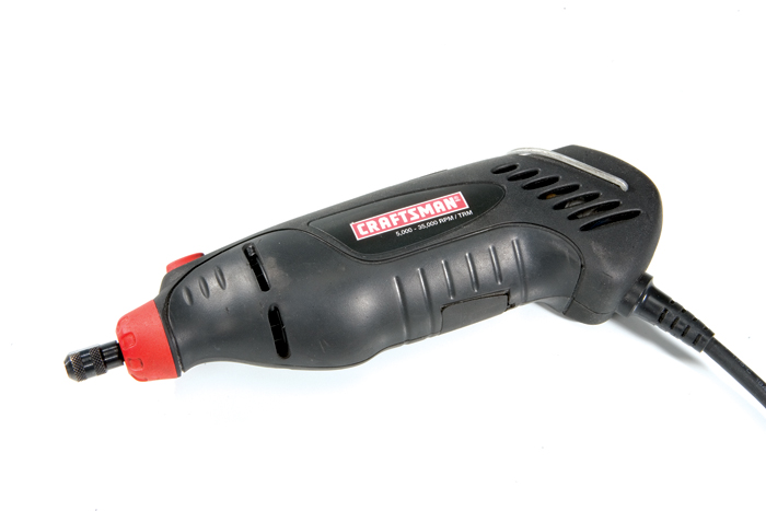
There are literally hundreds of uses for a roto-tool in regards to RC, and each is more valuable than the next. With adjustable speeds and a multitude of bits available, you can cut, sand, polish and grind just about anything. Dremel makes excellent roto-tools and is the go-to rig for RC.
Soldering station
Checkpoint Soldering Station
While a cheap soldering iron is sufficient for portability, investing in a soldering station is a wise investment. They have variable output, apply heat evenly and offer many replacement parts and tips.
Body reamer
body reamer
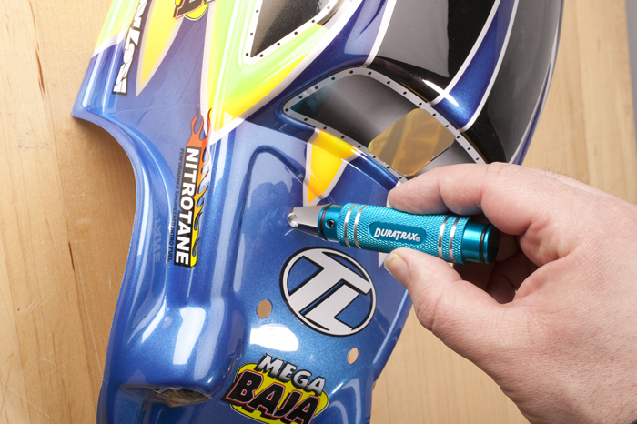
Using a body reamer, instead of a drill, is a much better method for cutting bodies. Buying an expensive body reamer will make reaming tasks easier, results in cleaner cuts and allows you to ream holes precisely and smoothly.
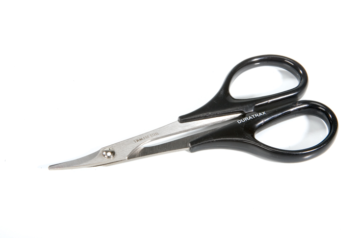
Lexan scissors
lexan scissors
Investing in a good set of curved Lexan scissors will make cutting bodies much easier. Straight scissors pinch Lexan and are difficult to make circular cuts with, while the curved scissors cut the plastic clean and allow for easy straight and curved cuts.
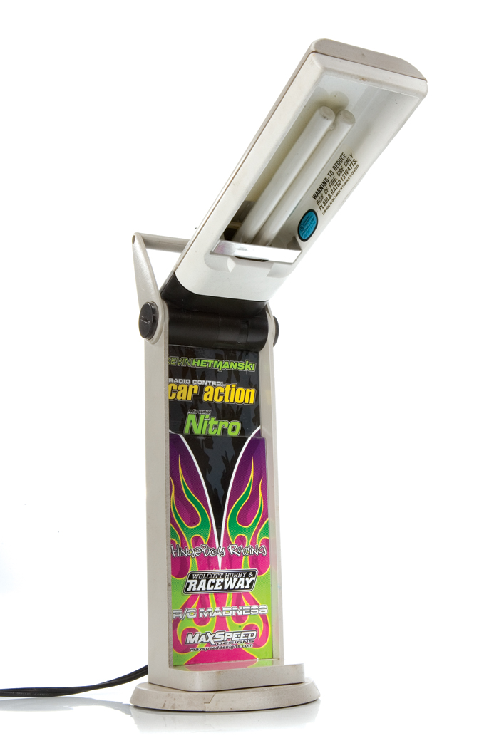
Pit light
pit light
Keeping your pit area well-lit is extremely important when working with small, intricate parts. The soft, bright light will prevent eyestrain, and an illuminated work area will prevent you from losing small parts.
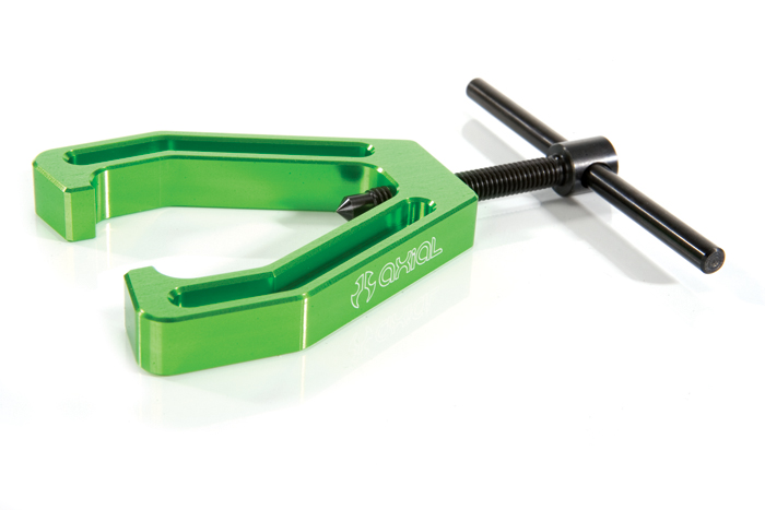
Flywheel puller
flywheel puller
Purchasing an anodized flywheel puller is a must for any nitro wrencher. It is integral when disassembling a clutch or engine and is a much better alternative to banging on the flywheel to try and free it from the crankshaft.
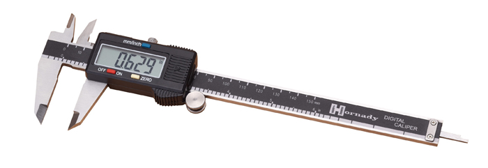
Digital calipers
digital-calipers
For measuring duties, nothing bets a nice set of digital calipers. You should always use digital calipers when accuracy is important: shock length, preload, turnbuckles, measuring fasteners, ride height, and the list keeps going.
Setup board
setup board
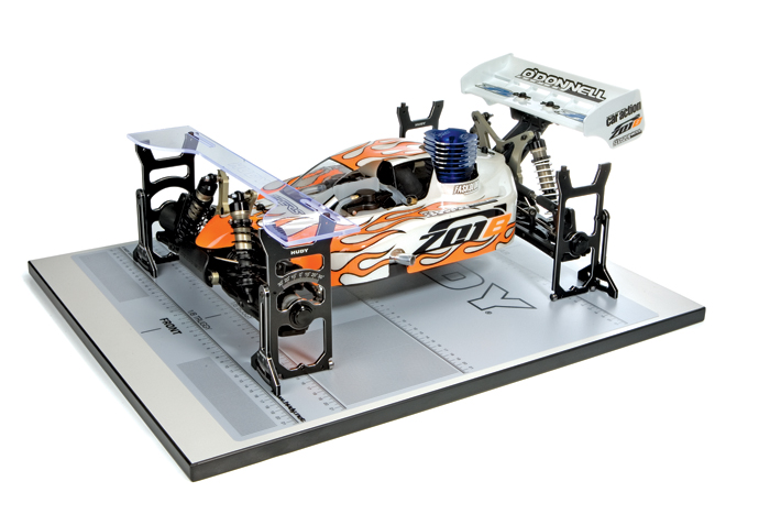
Especially if you are on on-road enthusiast, purchasing a setup board and hardware is valuable in maintaining a correct setup: toe, caster, camber, ride height, and more. Although the margin of error is a bit larger, off-road racers also benefit from using a setup board.
Digital temperature gauge
digital temp gun
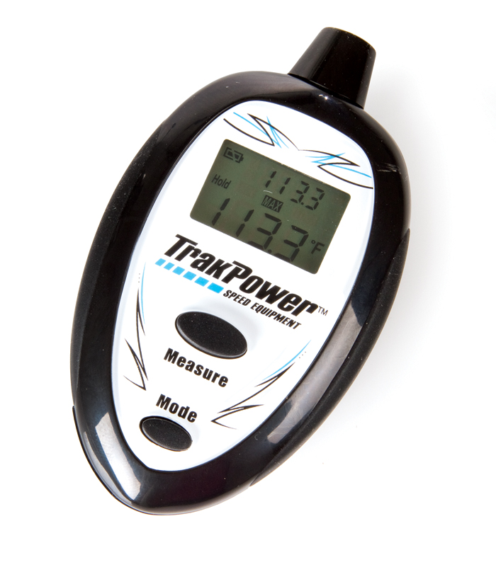
Although there are some cheap ones on the market, throwing-down on a high-quality digital temperature gauge will give much more accurate readings. Since a matter of ten degrees can make a big difference, accuracy is important in engine tuning and monitoring battery and electric motor temperatures as well.
Soldering jig
soldering jig
With a multitude of different performance connectors currently available on the market, manufacturers are now producing all-in-one soldering jigs that hold connectors in place for soldering purposes. Some of the jigs even hold different gauged wires. Using a soldering jig will result in cleaner soldering jobs, which will result in greater electrical efficiency and performance, not to mention a lower chance of burning your fingers!

How To: Tune a Nitro Engine – Carb Tech Secrets Revealed!

by 
By far the steepest learning curve for a nitro rookie is learning how to tune a carburetor. It can be awkward at first, but with a little effort, you’ll get it and never forget how to do it. Before we start adjusting needle valves, let’s consider the role of the carburetor and how it works. Properly tuning a carb is much easier once you understand how it functions.
HOW CARB TYPES REGULATE AIR/FUEL MIXTURE
A rotary carb contains a horizontal “barrel” that has a vertical hole drilled through it. As the barrel is rotated from the open position (the hole in the barrel is aligned with the hole in the carb body) to closed, the airflow that is pulled into the engine is reduced and, as a result, the engine speed is reduced.
In some cases, the barrel not only rotates, but it also moves slightly from one side of the carb housing to the other – an action similar to a screw being twisted from a threaded hole. This sideways motion operates the low-speed needle by pushing it into or out of the spraybar.
The slide-valve carb components are similar to those on a rotary-barrel carb, but they’re just arranged differently. Instead of having a vertical hole drilled through it, the slide valve is a solid piece of plastic or metal. To regulate airflow, as the piece slides into and out of the carb’s venturi, it allows air to pass by. As with the rotary type, the slider contains the low-speed needle valve to control the fuel/air ratios for idle and low throttle settings. As the slider is further closed, the low-speed needle valve reduces fuel delivery and the air flow is reduced; as a result, the engine slows down.
WHAT CARBURETORS DO
All carburetors control engine speed by varying the amounts of air and fuel that enter the engine. In RC 2-stroke engines, either a rotary-barrel or slide-valve carb is used to control this vital air/fuel mixture; the valve controls the amount of air fed into the engine, and the fuel-mixture needle, or needles, controls the fuel delivery. As your vehicle’s transmitter trigger is pulled, the throttle servo either rotates the throttle barrel (on a rotary carb) or retracts the slide valve (on a slide carb) to feed more air into the engine to increase power and speed. Similarly, when the carb is closed, air and fuel intakes are restricted and, consequently, the engine slows down.
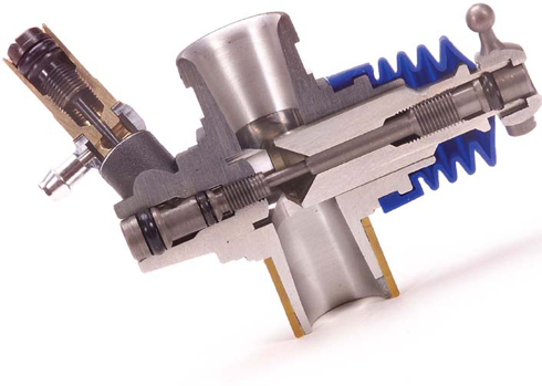
This cutaway picture of the carb illustrates how fuel flows through the needle valves (shown by the blue highlighted areas). Note how the tapered needles (circled) fit into tapered opening to control fuel flow.
A slide carb; it’s easily recognized by its accordion-style rubber boot.
A rotary-barrel carb. The long control arm on the right is the giveaway.
This cutaway shows a rotary carb in action. at full throttle, the incoming fuel/air mixture makes a straight shot through the carb.
The barrel rotates to make the opening smaller, thus reducing the engine’s rpm.
SINGLE-, 2- AND 3-NEEDLE CARBS
All RC engines use either rotary-barrel or slide-valve carburetors, but there’s an additional level of distinction within these groups: the number of tuning needles they have. The most basic engines have a single needle that adjusts the fuel mixture, but the majority of engines use two needles: one for a low-rpm mixture setting and another for high-rpm adjustments. Some high-performance racing designs have three independent needles to adjust the low-, midrange- and high-rpm mixture settings. Next, we’ll look at the pros and cons of each needle configuration and focus on tuning advice for all three varieties.
SINGLE-NEEDLE CARBS
Single-needle carbs are often billed as “easier to tune” because there is only a single needle to adjust, but tuning a single-needle carb for good performance over a broad rpm range can actually be a challenge. Single-needle carbs have only one setting, so the engine generally runs well in a narrow rpm range, but any engine speeds above or below that range will suffer from a less than ideal air/fuel mixture.
An engine that’s tuned as well as it can be with a single-needle carb may run reasonably well in the midrange, but it’s generally very rich at idle and very lean at high speeds. If the engine idles for too long, it can stall because the mixture is rich at low rpm, and running in the high rpm range may cause excessive heat buildup because the mixture is too lean at those speeds. You can adjust the needle to the rich side to compensate for the lean high speed, but then the low speed becomes even more rich, and that makes it difficult for the engine to idle for even a couple of seconds. Tuning a single-needle carb is a question of compromise. Here’s what to do.
On a single-needle carburetor, there is only a high-end needle. The needle usually has a tall, knurled body that makes it easy to twist by hand, and there is often a slot for a screwdriver tip in the top of the needle body for body-on adjustments.
Tuning a single-needle carb. The best way to adjust a single-needle carb for all-around performance is to start with a rich but drivable setting and then turn the tuning needle clockwise (more lean) in 1/8-turn increments until the engine’s performance feels well suited to your running conditions. If the engine misses, sputters or stops at full throttle, richen the mixture 1/8 turn at a time until these problems cease.
Getting an engine to run at its best is relative for those that have a single-needle carb. The final setting is always a compromise between allowing the engine to idle for a few seconds and yet still have enough fuel to prevent a lean condition at high speed.
Engine temperature should be your guide when tuning engines with single-needle carbs. That’s not the case when tuning multiple needles for performance, but there’s little choice with a single needle, and it’s best to err toward the side of caution so the engine will live to fight another day. Keeping temps below the 280-degree F mark is a reasonable goal.
2-NEEDLE CARBS
Two-needle carbs offer an enormous performance advantage over their single-needle counterparts. Two-needle carbs allow better acceleration and idling because the low-speed mixture can be leaned independently of the high-speed mixture. When properly tuned, a 2-needle carb engine will feel more on the pipe through the whole rpm range than any single-needle carb engine you’ve ever driven!
The low-speed needle is on the rotary lever side (on rotary carbs), or on the slider side (on slide carbs) of the carb body. It travels with the slide valve or rotary barrel and gradually enters the spraybar as the throttle is closed. The low-speed needle valve affects fuel delivery from idle to approximately 1/4 throttle, and then the high-speed needle valve takes over. When given an option, always choose a 2-needle carb over a single-needle carb.
For best engine performance throughout the usable rpm range, a 2-needle carb is the minimum requirement. In the carb body, the low-end needle is opposite the valve mechanism. On slide carbs, there is often another screw head on the end of the slide valve, but this screw is not a needle; it is used to set the position of the ball joint.
Tuning a 2-needle carb. First – and most important – tune the high-speed needle for best top-end performance. Because the high-speed needle also controls how much fuel gets to the low-speed needle (the fuel line feeds fuel into the high-speed needle, which in turn feeds the low-speed needle), this is the most important adjustment. When your car or truck performs well at full throttle, you can begin to adjust the low-speed needle valve for reliable idle and crisp acceleration. To prevent the engine from dying under braking, use the idle-stop screw to maintain approximately a 1mm gap in the carb opening even when it’s “closed.”
Warm the engine completely by running it hard for a few minutes. If, when it has warmed up, its idle speed gradually increases on its own before it stalls, your low-speed-needle setting is too lean. Similarly, if your engine stutters and misses when given full throttle from a complete resting stop, your high-speed and low-speed needles are set too lean. When in doubt, richen both needles considerably and start over by properly tuning the high-speed needle. Then re-tune the engine until the idle rpm level off.
If you bring your vehicle in and idle it for a few seconds, and during that time the idle rpm gradually drops off until the engine dies (BWAAAAAaaaaaaeeeeerrrr – to nothing), your low-speed needle is probably too rich. Lean the low-speed needle 1/8 turn clockwise until a reliable idle is attained. Properly tuning the low-speed needle will produce a reliable idle and crisp acceleration without much bogging.
3-NEEDLE CARBS
For the most part, 3-needle carbs are the same as 2-needle carbs. They function identically, but the 3-needle carb has an adjustable spraybar in addition to an adjustable needle, so the third “needle” isn’t really a needle; it’s an adjustable spraybar.
What does it do? A 2-needle carb gives you two ranges to work with to provide the engine with the proper air/fuel mixture – low-speed and high-speed adjustments.
A 3-needle carb allows a weak third option; it’s a little weak because it isn’t actually a needle. The spraybar and the needle are adjusted at the same time to determine at what throttle position the spraybar (third needle) is exposed to direct airflow, and that creates a subtle increase the amount of fuel flow.
A 3-needle carb’s high- and low-end needles are in the usual locations, and the third needle is on the valve side of the carb. Three-needle carburetors represent the ultimate in tunability but take more time to dial in properly. A correctly tuned engine with a 2-needle carb will outperform the same engine with an improperly tuned 3-needle carb, so let your skills and experience guide your carb selection rather than adopting a “more-needles-are-better” approach.
Tuning a 3-needle carb. Initially, you should tune your 3-needle-equipped engine in the same way as a 2-needle carb is tuned. When you’re pleased with the engine’s performance, pay very close attention to the transition from low speed to high speed. Does it sputter, lag or “fall off the pipe” in the middle of the rpm range? If so, you should adjust the third needle.
To adjust the third needle, turn both the low-speed needle and the third needle the same number of turns in the same direction (1/4 turn at a time). This retains the idle setting but alters the midrange response. Run the engine for a few minutes and re-tune if necessary. When tuning, remember to make small adjustments, so that you’ll know which change affected performance.
It’s a good idea for inexperienced tuners to leave the third needle setting alone, as it requires a very experienced driver to even feel the difference at all. There’s a risk that the engine will run poorly if you tune the third needle incorrectly. It’s best to treat your carb as if it’s a 2-needle until you gain more experience.
NOTHING TO FEAR
Tuning an RC carburetor is not an exact science; you won’t find anyone at the track saying “Let’s see: it’s 65 degrees, relative humidity is 70 percent, and I’m running 20 percent fuel, so I need to be two turns out on the low end and three turns out on the high end.” Understanding how the carburetor functions is an invaluable asset in your quest for perfect power, but what really delivers results is when you couple your knowledge with experience. The more time you spend experimenting with your engine, the better you’ll become at tuning it. There’s no need to be afraid of needles!
ENGINE TUNING TERMS
LEAN To lean an engine means to reduce the amount of fuel (relative to the amount of air) entering the engine by turning a needle valve clockwise.
RICHEN Richening increases the amount of fuel (relative to the amount of air) entering the engine, by turning a needle valve counterclockwise. Richening an engine to obtain the proper air/fuel mixture will generally reduce engine temperature and increase lubrication.
NEEDLE VALVES These are the small screws found on the upper portion and sides of the carb body. These are used to adjust the fuel-to-air ratio.
SPRAYBAR This is the metering jet inside the carb body that mates with the low-speed/idle needle (when equipped). They fit together like a tapered peg into a tapered hole.
ON THE PIPE A phrase that indicates an engine is running with an ideal tune and producing excellent power.
IF YOU REALLY WANT TO GET TECHNICAL
A fuel curve shows the ideal air/fuel ratio at any given speed on an engine’s rpm scale. Because ideal proportions vary with rpm and load changes, it’s important to tune your carb so that the air/fuel mixture is optimized as much as is possible.
This graph shows what most engine tuners already know: when the engine is started, it needs less fuel because its air intake is lower. Acceleration increases engine load, and a higher rpm means that more air goes into the engine; this means the engine needs more fuel to maintain the correct ratio of air to fuel. The increased fuel requirement tapers off only as the engine reaches the upper limits of its rpm range and transitions into a “cruise” mode during which hard acceleration isn’t possible because rpm have maxed out.
Understanding your engine’s fuel requirements can guide your approach to fuel-mixture adjustment.

How To: Get the most out of your brushless motor!

by 
How to understand brushless timing
Brushless motors have completely taken over racing, and pretty much everyone has switched to brushless. Most racers are hitting tracks with sensored 17.5 brushless setups, but  unlike their brushed 27-turn “stock” predecessors, these motors allow you to change the motor’s timing. The only problem is that motor timing is still a bit of a mystery to most racers, and in this case, knowledge is power. Here’s the scoop on how and when to adjust timing, so you can get the most possible power out of your brushless motor.
WHAT TIMING DOES
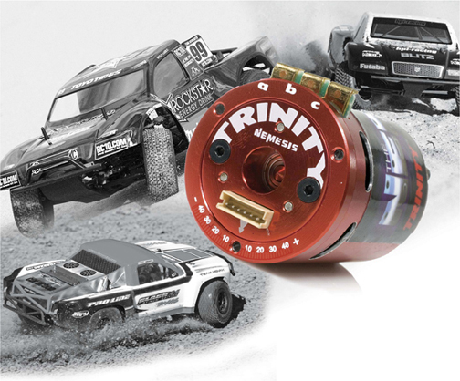
Brushless motor timing is the relationship between the motor’s sensors and the phases of the stator. Brushless motors react to increases and decreases in timing the same way as brushed motors, but most are a little less sensitive to changes. Increasing timing increases rpm and motor temps but decreases torque, efficiency and run time. Decreasing timing does, as expected, just the opposite. Timing changes are similar to gearing changes but are far more subtle.
KEY TIMING TERMS
  • EFFICIENCY: measurement of how much energy Is transformed into usable power
  • RPM: short for rotations per minute; a measurement of speed
  • TORQUE: measurement of force, specifically rotational power.
HOW TIMING IS ADJUSTED

There are two ways to adjust timing depending on the type of brushless system you’re using. Many speed controls feature software that offers the option of changing the motor’s timing, and you can also physically adjust the timing on the motor. Typically, you loosen, but don’t remove, three screws on the endbell and rotate the endbell counter clockwise to align timing marks on the endbell and can. Some systems allow you to adjust timing via the controller as well as on the motor.
WHEN TO CHANGE TIMING

The easiest way to know if you need to change timing is to use a temp gun. To help get an accurate temp reading, add a small piece of black tape or even black paint to your brushless motor. The first thing you want to check is that after a full-length run (not two minutes) the motor is below 180 degrees F. This is the threshold for most motors. At 180 degrees and above, most motors will lose power and potentially fail. Even if a motor doesn’t fail, excessive heat permanently causes magnets to lose their strength. If your motor is at or near 180 degrees F, try reducing motor timing, and recheck it. If that doesn’t work, it will be necessary to change gearing with a smaller pinion.
After you’ve determined that you aren’t running too hot, make sure you aren’t running too cool. If, after a full-length run, your motor is at less than 140 degrees F, the motor is probably not making its maximum power. The “sweet spot” is usually at about 160 degrees F. Try to increase timing before you make a gearing change.
Another way to use timing is when a single-tooth pinion change is too much of a change. Motor timing is usually the perfect way to split the difference.
If you feel your motor is fading near the end of a run, regardless of the motor’s temp lower the timing. This is typical during the hot summer months. Generally, when outside temps are in the 90s and above, try lower timing settings.
In the same way that many professional off-road racers use gearing to tune for available traction (you knew that, right?), motor timing can be used to help on a slick track. Instead of going up a pinion size, first try to increase timing. This will reduce the low-end power and decrease the tendency of the tires to break traction.

How To: Remove Anodizing From Aluminum Parts

By 
An easy way to change up the look of your vehicle
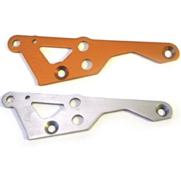
Many RC cars these days are identifiable by their anodized aluminum parts. For instance, HPI almost always uses purple or orange; Traxxas vehicles use blue anodized parts and Axial went with green. Sometimes you may be into a vehicle, but not the color used to coat the aluminum parts and that can be a deal breaker for you when purchasing a vehicle. Spending money on new aluminum components in the color of your preference will cost you even more money in the end. We have found a cheap method of removing the color from your aluminum components in a nontoxic way so your parts will be back to their raw silver color. They can then be re-anodized, powder coated or whatever else you decide. The whole process only takes about 15 minutes to complete, and here’s how you do it.
WHAT DO YOU USE?
deano3
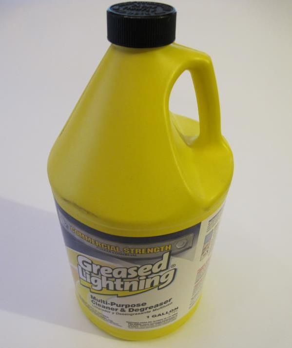
Purchase some commercial-strength Greased lightning cleaner and degreaser to remove the anodizing from your parts.
Anodizing can be removed by sanding the components with various grades of sandpaper starting from a rough grit and ending with a fine grit. This process requires a lot of elbow grease, is time consuming and really only works on aluminum plate due to the easy access to its flat surface. Once you get into machined components such as suspension arms or hubs, the complexity of their shape makes sanding difficult. You can take your parts off to a sand blaster and that will take care of the anodizing in an instant. However, the downside is that you have to search for a sandblasting company to take care of the components, it will cost money to make that happen and the finish of the parts afterward will be rough and dull. The best way we found to remove anodizing is by soaking them in a product called Greased Lightning. It comes in a variety of forms and the commercial grade bottle is what you are looking for when removing anodizing.
GET STARTED
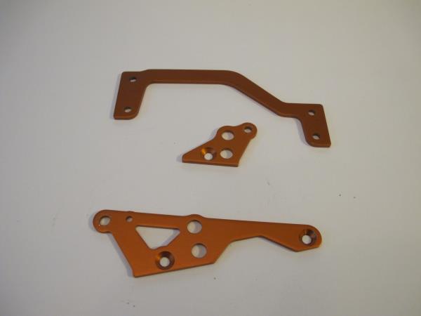
Remove all anodized parts from your vehicle and deep clean the items to rid them of any dirt, debris and grease.
Start by removing all of the anodized aluminum components from your vehicle. Depending on what parts you want to de-anodize, it may require completely disassembling your vehicle to make it happen. Remember to keep your parts organized during this process so that you’ll have an easy time putting things back together when you’re done. If you’re starting with a new vehicle, your parts will be ready to go. If you’re dealing with an old vehicle, you need to take the time to clean the parts. While you are at it, look them over and make sure that they aren’t damaged. If they are bent or scratched, now’s the time to replace them.
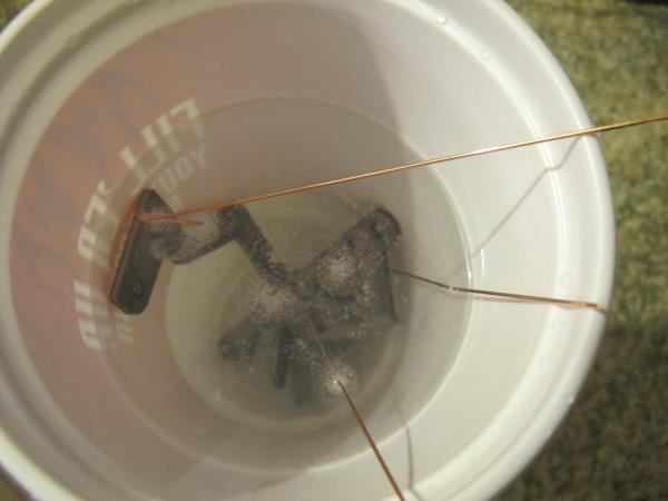
Wrap a piece of wire or a zip-tie around the part, which will make it easier to place the part in the solution and remove it - the degreaser is not good for your skin!
Wrap a piece of wire or a zip-tie around the part, which will make it easier to place the part in the solution and remove it – the degreaser is not good for your skin!
THE REMOVAL PROCESS
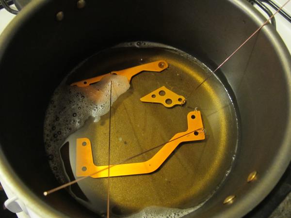
Start by loading your parts into your old pan and fill the pan with Greased Lightning. Add just enough solution to cover the parts and make sure that you don’t crowd them in the pan. Stripping a few parts at a time is more time consuming but will give you better results in the end. Let the parts sit in the pan until the coloring fades away.
Pour enough of the Greased lightning solution into an old pan to completely submerge all components. Wrap a wire or zip-tie around the components to lower and remove them from the solution.
Pour enough of the Greased lightning solution into an old pan to completely submerge all components.
Allow the components to rest in the solution until the color starts to fade away. Agitating the components will help to free up and dissipate the color.
While the parts are sitting, fill another pan with clean water so you can dip the parts in after to avoid oxidation of the now bare aluminum. Clean the parts with soap and water to remove any leftover cleaner and you’re ready to go.
When you remove the components from the solution, immediately place them in a container of clean water (even a plastic cup will do) to avoid oxidation of the aluminum.
Some of the components may not shed their color easily so it may require some scrubbing with a Scotch-Brite pad.
Use some steel wool or a Scotch-Brite pad to remove any stubborn anodizing.
WHAT NOW?
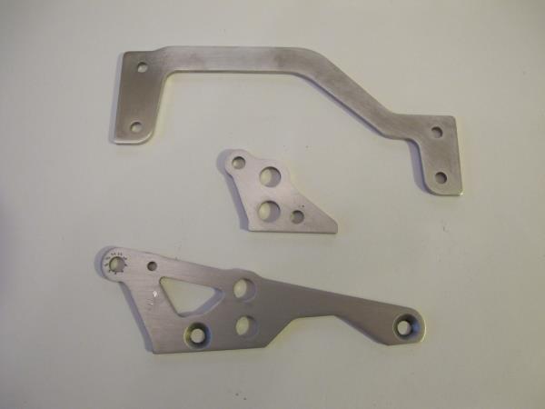
After you wash and dry the parts, they are ready to be powder coated, anodized a different color, polished or run in a raw state.
Now that your parts are stripped of their anodized color, you’ll need to decide how to finish them off. Some of you may be happy with the parts as they come out of the solution, but you have some options. You can polish the parts to give them a chrome look and add some bling to your vehicle. Maybe you want them to be anodized a color that doesn’t get used often in the RC world. That can be done and it requires you to find a local anodizing shop and hopefully, they will have a color that will make your parts stand out. This is a costly process but you can reduce the cost if you can wait for a time when they have other parts to anodize that same color. Powder coating the parts is another option and you’ll basically have to go through the same process that you do if you go for anodizing. The one thing that you need to remember is that when parts are powder coated, the coating adds thickness to that part. So some areas may have to be masked before the powder-coat process. It’s easier to do that before than having to remove the hardened coating after the process has been done. The last option is to paint your parts. Paint, however, is easy to scratch, so try to use paint on parts that aren’t easily reached.

How To: Boost the Strength of Plastic Parts

by 
Many of the plastic parts that make up RC vehicles, especially suspension parts, are made of nylon or a plastic formulation that includes nylon. Nylon is “hygroscopic,” which means it absorbs moisture.  This occurs naturally, as nylon will absorb moisture from the air (and also dry out, when the air is dry). The greater the amount of absorbed water in the plastic, the more flexible (and thus, more durable) it becomes. The natural absorption of moisture occurs over months–unless you speed it up.
RPM_arms
Plastic parts made of nylon, or those having nylon in their formulation (such as these RPM arms), can benefit from boiling.
Plastic parts that contain nylon can be boiled to ensure maximum water content and maximum durability. This is not generally necessary for new parts, but there are exceptions. According to Richard Royal of RPM RC Productsthe go-to maker of super-tough molded replacement parts, the high pressure (over 7,000 psi) and heat of the injection molding process can create stress inside the part as certain areas cool more quickly than others. Boiling relieves this stress. If you find yourself frequently breaking certain parts, boiling your next replacements before installation might make a difference.
Boiling can can also benefit older vehicles–especially vintage finds that may have spent years getting dryer and more brittle as they baked in attics or garages. Here’s how to boil the toughness back in:

1. Bring a pot of water to a rapid boil. Select a pot that’s large enough to submerge your parts.
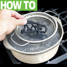
Use a strainer to keep the parts off the bottom of the pot.
2. Place your parts into the water. Use a small metal strainer placed inside the bowl to prevent the plastics from sitting on the bottom of the pot, which could lead to melting.

Timer
Three minutes is all you need
3. Allow the parts to boil for 3 minutes. Set a timer to remind yourself when the parts are “done.” Boiling the parts longer won’t make them any stronger; once the parts have absorbed all the water they can, extra time in the water makes no difference.

Cool off, dry off, reinstall.
4. Remove the parts and allow to cool. Let the parts cool to room temperature on their own, don’t put them in the fridge or freezer. Once cool, the parts are ready for installation and use.

Summit_snow
Beware of cold when running freshly boiled parts
COLD WEATHER WARNING
Use caution if you plan to use freshly boiled parts in freezing weather; according to Richard, the moisture inside the arm will freeze, making the part even more brittle than it was before you boiled it.

WHAT ABOUT OTHER PLASTICS?
Boiling will only benefit nylon and nylon blends. Other types of plastics will either be unaffected, or may warp or shrink–not good. When in doubt, boil a broken part first or a scrap of the “tree” (actual term: sprue) the new part came from before boiling a good part. If the material appears unaffected, go for it–boiling the part won’t make it weaker, and will likely make it more flexible and less prone to breakage.

THIS is How You Hold Onto a Turnbuckle

When you get involved in this great hobby of ours there’s no doubt that you need to have a good set of tools to not only do the job right  but to make wrenching on your vehicle much easier. Over the years I have been lucky enough to have some of the best tools in the business but I have never really had a tool that  helped me do the job that I like dislike the most: building turnbuckles.
No matter what tool I use I find myself fighting to keep the turnbuckle stable enough to properly apply torque to the rod end and get it installed. I eventually got to the point where I would use the chuck of my lathe to hold the turnbuckle while I twist the rod end on but if it was a short turnbuckle it was only good for one side.
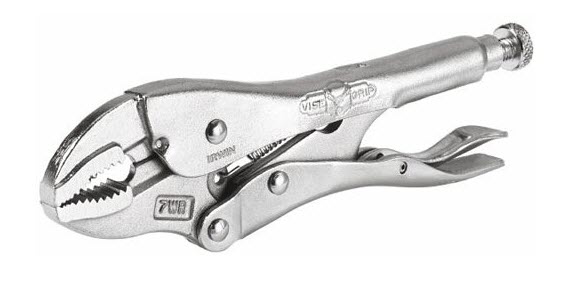
Then I discovered that I could use a pair of locking pliers (AKA Vice Grips) to do the job of holding the turnbuckle. Vice Grips adjust easily to fit the flats properly, and does a great job of holding onto the turnbuckle without requiring sheer hand power to hold the turnbuckle tightly. Vice Grips come in different shapes and sizes and are handy for all kinds of home repair work, but for RC duty I went with the 5 inch pair so they easily fit into my tool box.
VG
Vice Grips are great for holding onto any size turnbuckle. Spend a few extra bucks for genuine Vice Grips instead of getting knock-offs–quality counts.
VG2
Line up the jaws with the flat on the turnbuckle and clamp down. The turnbuckle won’t go anywhere until you pop open the Vice Grips.